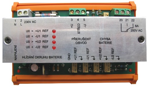
HOB - Battery Loop Watch-Dog
monitoring failures in a battery loop in DC backup power-supplies

Description
The HOB relay is used in a DC backup power-supplies to monitor a circuit of a battery that is connected in parallel to the rectifier output. In the used mode the rectifier covers complete current demand and the battery does not participate on it at all. The used way of monitoring informs an user about possible problems in a battery loop. The failure is indicated by the status of an internal relay and the relevant information is shown on the switchover contact.
The monitoring is carried out in two levels. The first level is used for signalling of inbalances of individual battery blocks, the second level usually signalizes the interruption of a battery loop.
The HOB relay works on a principle of comparing of two voltage levels. One voltage level is given by the exact voltage center at the rectifier output. The second voltage level is brought from the center of a battery. There are usually fuses, wiring and jumpers between battery blocks placed between the rectifier output and a battery. In case that there is no failure, there is no difference between these voltages and the HOB relay is not active (switched-off).
In case that a failure of a fuse occurs, for instance, the battery is not charged and its voltage drops. The voltage of the battery center against plus or minus pole drops too at the same time. Thereby the voltage difference starts to arise at the inputs of the HOB comparing circuitry. As soon as the difference exceeds the preset level, the internal output relay switches on, and a particular LED that corresponds to the polarity of the exceeded voltage of the level 1 or 2 lights-up too.
The HOB relay is supplied from the mains. An internal DC power-supply makes a symetric voltage for the internal circuitry as well makes the set of the reference voltages for setting-up of all individual voltage levels.
All the connection points are made as screw terminals and are labeled on the front panel:
- 1 N – mains
- 2 L – mains
- 3 +U – plus pole of the rectifier output
- 4 STŘED – center of the battery voltage
- 5 –U – minus pole of the rectifier output
- 22 – switchover contact common pole
- 21 – closing contact against 22 terminal
- 20 – breaking contact against 22 terminal
Features
- two levels of sampling
- easy setup of the reference levels
- optical signalling by the LEDs
- potential-free switchover contact 8A/250VAC
- low self power consumption
- DIN bar montable
Application
- monitoring failures in a battery loop
- DC back-up power supplies


